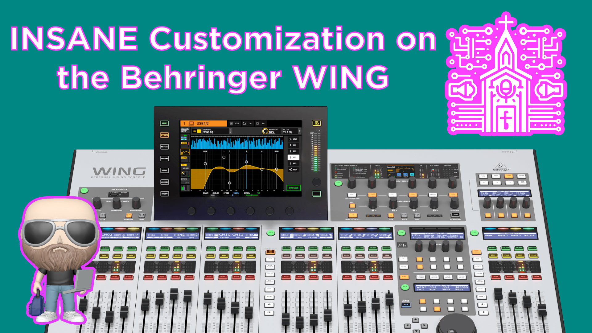
Insane Customization on the Behringer WING – Build Your Own Layout!
Unlocking the Power of Custom Layer Configuration on the Behringer Wing Console
The Behringer Wing is more than just a digital mixing console—it’s a powerhouse of customization. If you’re transitioning from another console or even if you’ve been using the Wing for a while without diving deep into its customization capabilities, this article will show you how flexible the system truly is.
One of the most powerful features of the Behringer Wing is the ability to fully customize what appears on each fader layer—across every section of the board. This means you can tailor your mix layout to suit your workflow, whether you’re handling front-of-house, broadcast mix, or monitors in a complex live church environment.
This guide breaks down the concept of layer layouts on the Behringer Wing console, explains the value of customizing it, and gives you step-by-step instructions on how to set it up effectively.
Understanding the Layout: Default Layer Views
Upon powering up your Behringer Wing, you’re greeted with fader layers that seem to be assigned in linear channel blocks. This might look familiar if you’re coming from consoles like the X32, M32, or Yamaha QL/CL systems. But here’s the core difference: while those consoles allow for some bank modifications, the Wing lets you change absolutely everything.
By default, here is how the surface is grouped:
- Left Bank (Channels 1–12, 13–24, 25–36, 37–40): These typically represent inputs 1 through 40.
- Aux Inputs: Combined into one layer for aux sources (e.g., mobile devices, Bluetooth, Dante virtual sound cards).
- Bus Masters: 16 total bus outputs.
- User Layers 1 & 2: Fully customizable for displaying any combination of inputs, buses, DCAs, matrices, etc.
In the center section, additional layers include:
- DCA Layer: Defaults to DCA 1 through 8.
- Main/Matrix Layer: For controlling left, right, center (or mono), and matrix outputs.
- Aux Inputs Layer: Again, for auxiliary sources like stereo tracks or specialty inputs.
- Bus Master User Layers 1 & 2: Fully customizable and independent from the left and right banks.
Finally, the right-hand side faders replicate the same flexibility and can mirror or diverge from the left and center layouts, making it completely modular.
The Core Concept: “Anything Anywhere”
Here’s the key takeaway—you can literally place any source on any fader in any layer. That means:
- Put Input Channel 1 right next to Bus 1.
- Put a Matrix next to a DCA.
- Put a Vocal Delay FX Return next to your Lead Vocal Input.
- Place drum channels on Layer 1 for quick access, even if they appear earlier in the routing.
Whether you’re building a front-of-house layer, a streaming broadcast mix layout, or a custom monitor layout, this is incredibly powerful.
How to Customize Your Layers
You don’t need to enter any deep menus or perform complex routing to change layouts. Here’s how to do it in a few simple steps:
Step-by-Step: Customizing User Layer on Behringer Wing
Step 1: Choose the Section to Customize
Each bank—Left, Center, or Right—has a corresponding VIEW button. Press the VIEW button on the section you want to edit. For example, “User Layer 1” on the Left Bank.
Step 2: Enter Config Mode
Once you’re viewing a user layer (e.g., User Layer 1), look at the touchscreen and press the CONFIG tab. This gives you the editing interface.
Step 3: Drag and Drop Channels
You’ll now see:
- A full list of available channel types: Inputs, Buses, DCAs, Matrices, Mains, etc.
- Your current strip assignments at the bottom of the screen.
To customize:
- Tap and hold a source (e.g., Channel 3).
- Drag it down to any fader position.
- Want to insert DCA 1 next to your Lead Vocal? Drag and drop that too.
- Need fast access to Matrix 2? Just place it in the next available slot.
You are not changing the patch or signal flow—you’re only surfacing the controls you want to see. The rest remains fully active in the background.
Practical Application: Mixing Strategy
Here’s a practical way to think about it: Instead of flipping layers during a live set, build a “mixing surface” that matches how you think and mix in real-time.
Example Custom Layer:
- Fader 1: Lead Vocal Input (Ch 8)
- Fader 2: Vocal DCA (controlling all BGVs)
- Fader 3: Drums DCA
- Fader 4: Vocal Delay FX Return
- Fader 5: Acoustic Guitar (Ch 12)
- Fader 6: Electric Guitar Bus (grouped stereo)
- Fader 7: Click Track (from Dante)
- Fader 8: Pastor Mic
This eliminates the need to move between multiple layers during a service. Everything is exactly where you want it—or rather, where your hand wants it.
Advanced Tip: Hidden or Background Channels
A useful technique is to let channels live in the routing table without assigning them to faders. These can include:
- Spare mic lines not used in today’s service
- Instrument or laptop inputs for visiting artists
- Unused FX returns
Because not all channels need a physical fader presence all the time, you can declutter your surface while retaining full routing capability.
Best Practices for Layer Design
- Group related items: Use DCAs and buses to control groups (Drums, Vocals, FX).
- Surface high-priority channels: Put Lead Mics, FX Returns, and Clicks right at your fingers.
- Label everything clearly: It’s critical during a fast-paced worship set.
- Keep User Layers consistent week to week: Unless your band setup changes drastically, avoid constant re-layouts.
- Build layout templates and save them with your show files for quick recalls.
Conclusion: Total Control in Your Hands
If you’ve ever fumbled through layers to find a mute or adjust a solo during a live event, you’ll understand how game-changing this feature is. The Behringer Wing doesn’t just allow custom layouts—it encourages them.
By learning to design a workflow-centric surface, you’ll significantly boost your efficiency, confidence, and mix quality during worship services or live broadcasts.
Harness the full customization power of the Behringer Wing, and start mixing smarter—not harder.